


-
Due to its advantages, such as a high thermal conductivity, the good thermal stress resistance and excellent radiation resistance, the reduced-activation ferritic/martensitic(RAFM) steel has been considered as a prime candidate structural material for future advanced nuclear energy systems[1]. A new kind of RAFM steel, SIMP steel was cooperatively developed by the Institute of Modern Physics(IMP) and the Institute of Metal Research, Chinese Academy of Sciences(CAS), China, not only to promote its radiation resistance[2-7], but also to improve its high temperature oxidation resistance and liquid metal corrosion resistance[2]. It has been considered as a candidate structural material for the future accelerator driven subcritical system(ADS).
In the future ADS systems, the structural materials will suffer from the high-energy and high-flux neutron irradiation, resulting in displacement damages and a great number of gas atoms (i.e He and H) by nuclear transmutations in the structural materials. The simultaneous generation H and He can greatly affect the micro-structural evolution and degrade the properties of the materials strongly in most cases[8-11].
The effect of He on materials has been largely studied in the past years[8, 12-13]. For instance, at lower temperatures, He can assist bubble (or void) nucleation and accelerate the onset of swelling during the incubation period. At higher temperatures, The aggregation of He bubbles at the grain boundary may lead to the high temperature He embrittlement. Compared with He, H has been thought to have less impact due to its higher mobility. However, it has been reported that H could also stabilize the vacancies in the same way as He at lower temperatures[14]. More importantly, H retention can be enhanced by the presence of He bubbles[15]. Therefore, the effect of H must be considered. However, up to now, the influence of H on He behavior is not completely clear.
The thermal desorption spectroscopy(TDS) is a very useful tool for investigating the migration, trapping and desorption behavior of He in the materials[16]. In this study, the He thermal desorption behavior in SIMP steel irradiated with He+ and H2+ sequentially was investigated by TDS, and compared with that in SIMP steel irradiated with He+ alone. Combined with the results of scanning electron microscope(SEM) and transmission electron microscopy(TEM), the effect of H on He behaviors (including He bubble evolution and release) in the structural materials was studied.
-
A type of reduced activation martensitic steel named SIMP steel was employed in this study. Its chemical compositions and heat treatment conditions are shown in Table 1[2]. In this study, the size of the SIMP sample was 15 mm× 7 mm× 1.2 mm. Before irradiation, all samples were mechanically smoothed and polished to mirror-like surfaces firstly, and then were annealed at 600 ℃ for 1 h in a vacuum better than 1×10⁻⁴ Pa, to remove the work hardened surface layer and avoid its possible effect on the subsequent experiments.
Table 1. The chemical compositions of SIMP steel*.
Elements Mass fraction/% Elements Mass fraction/% C 0.22 Ta 0.12 Si 1.22 V 0.18 Cr 10.24 S 0.0 043 Mn 0.52 P 0.004 W 1.45 Fe Bal. * Normalizing 0.5 h at (1 040±10) ℃ and tempering 1.5 h at (760±10) ℃. -
The irradiation experiments were performed at the 320 kV multi-discipline research platform for highly charged ions in IMP, CAS, China. Two implantation models were carried out: (I) He+-alone irradiation, (II) He++H2+ sequential irradiation. All irradiation experiments were conducted at room temperature in a vacuum better than 1×10⁻⁵ Pa. In order to make H and He atoms deposit in the same depth range, the energy of He+ and H2+ ions was fixed at 130 and 160 keV, respectively. Therefore, there were sufficient interactions among H/He and displacement damage. The detailed parameters for all irradiations are indicated in Table 2.
Table 2. The detailed parameters in the He/H irradiation.
Samples Ions Energy/keV Fluences/(ions/cm2) Peak damage/dpa Peak atom fraction/% 1# (He) He+ 130 7.14×10¹⁶ 1.8 5 2# (He+H) He+ 130 7.14×10¹⁶ 1.8 5 H2+ 160 2.78×10¹⁶ 0.14 5 3# (He+H) He+ 130 7.14×10¹⁶ 1.8 5 H2+ 160 2.78×10¹⁷ 1.4 50 According to the fact that an H2+ ion with the energy of 160 keV can dissociate to produce two 80 keV H+ ions, when it crosses the sample surface[17], the depth profiles of displacement damage and H/He deposition concentration obtained by SRIM 2013 calculations[18] are shown in Fig. 1. In the SRIM calculations, the density of the target material was 7.865 g/cm3, and the threshold of displacement energy for both Fe and Cr was set at 40 eV[19]. Fig. 1 shows the deposition peaks of He and H ions are overlapped in the depth range of 200~500 nm. At the same time, the ratio of vacancy to He is indicated in Fig. 2, for the sake of later discussion about the influence of displacement damages on He release.
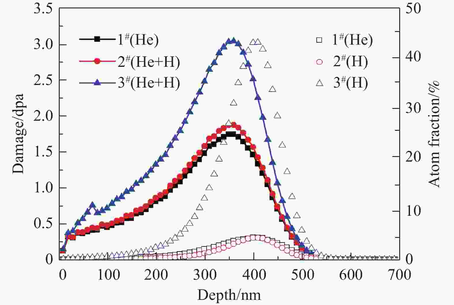
Figure 1. (color online)The depth profiles of damage level and He/H ions concentrations in the samples 1#, 2# and 3#, respectively, according to SRIM 2013 calculations.
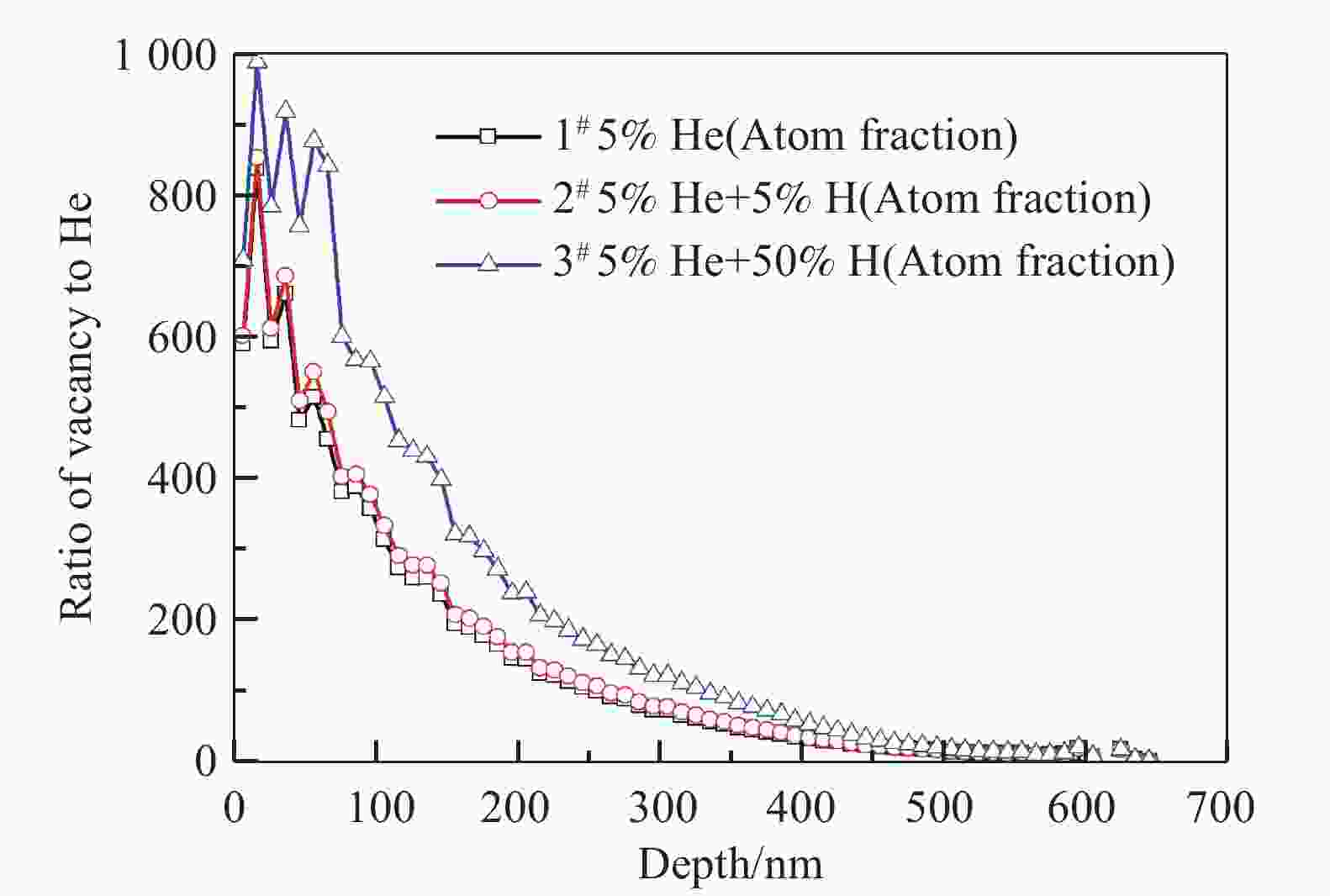
Figure 2. (color online)The ratio of vacancy to He in the samples 1#, 2# and 3#, respectively.
-
The TDS measurements were performed in the State key laboratory of Solid Lubrication, Lanzhou Institute of Chemical Physics, Chinese Academy of Sciences, Lanzhou, China. The heating process was divided into two stages. The first stage was increasing temperature from RT to 1 222 K at 5 K/min, and the second was holding the temperature at 1 222 K for 10 min. During heating, the vacuum in the TDS chamber was maintained below 1×10⁻⁵ Pa and the temperature was in-situ measured by thermocouples. The desorbed gas was monitored by a quadrupole mass spectrometer model Pfeiffer QME220. In the process of TDS measurements, some factors, such as the measurement of sample temperature, the background signal, may be the causes of the errors in TDS data. In order to reduce the errors, the TDS spectrum of a blank sample was measured to subtract the background signal, while all the samples were tested under the same conditions as possible. At the same time, the temperature difference between the sample and the furnace has been corrected.
-
In order to investigate the bubbles nucleation after irradiation, the cross-sectional TEM specimens with the thickness of about 70 nm were prepared using Focused Ion Beam(FIB) system, and then observed by TEM model FEI Tecnai G2 F20 S-TWIN operated at 200 kV. During the investigation of bubbles nucleation, the observation region was maintained in the depth range of 350~500 nm (near the peak of displacement damages) along the ions injection direction. Moreover, this region was far from grain boundaries or nano-particles, and where dislocation loops dispersed in a relatively homogenous way, to avoid their influence on the measurement of bubbles density. Furthermore, all of the TEM images were taken under the same defocus conditions(under-focus of 300 nm) for comparison of bubbles size. After TDS measurement, the retention of bubbles was investigated by TEM with a defocus value of 1.5 µm. Finally, the surface topography of the samples was observed by SEM model FEI Nova 450.
-
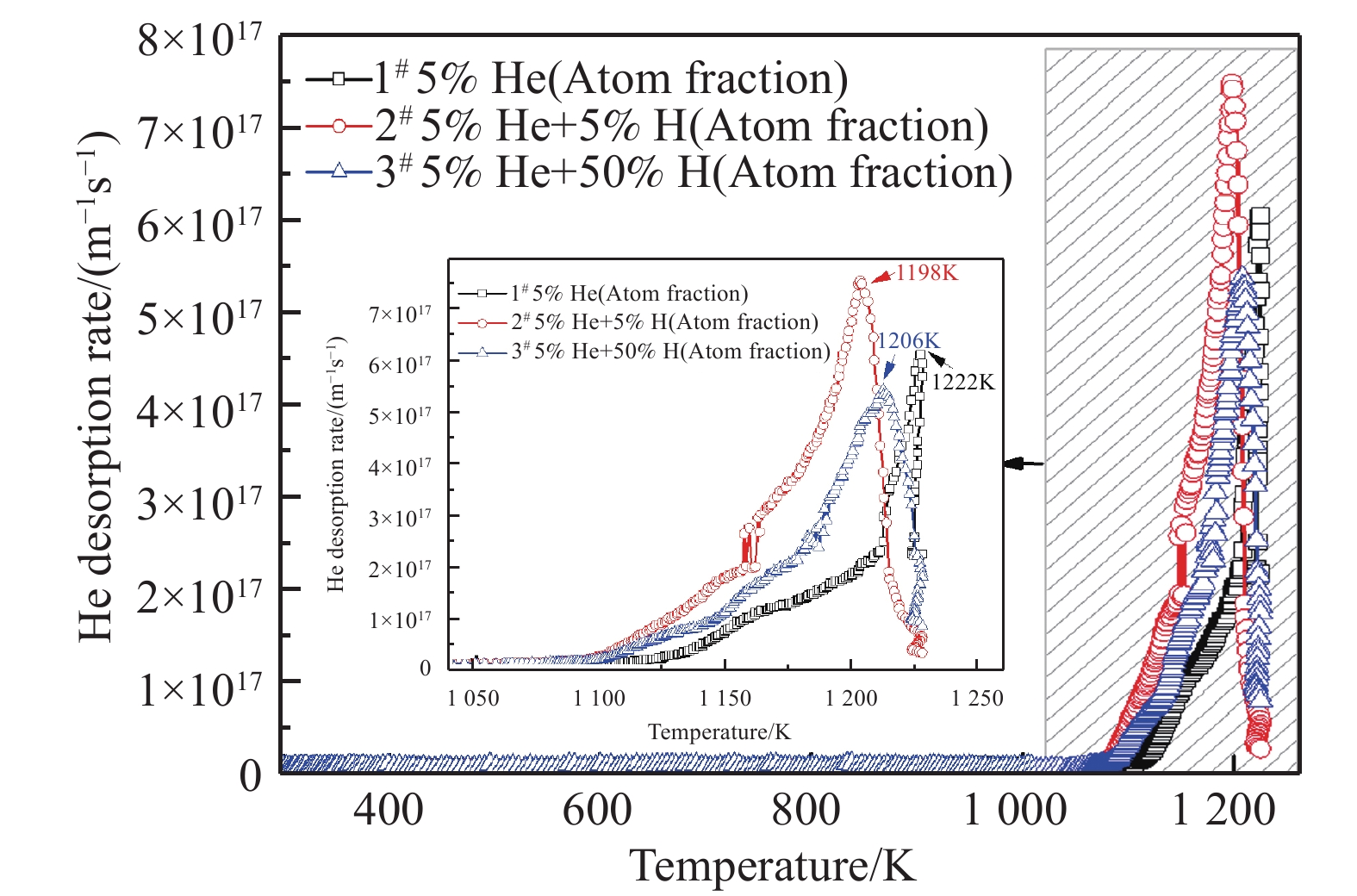
The He TDS spectra of the irradiated samples were shown in Fig. 3. As can be seen, a major peak was observed in all the irradiated samples. For the He+-alone irradiated sample, the major peak appeared at 1 222 K. It has been reported that He desorption behavior has been affected by the irradiation conditions, including the fluence, the energy, and the irradiation temperature. With an increase of He ions fluence, the fraction of He desorption at higher temperature increases[20-21]. When the fluence of He+ irradiation reaches 5×10¹⁶ ions/cm2, the release of He mainly occurs via the mechanism of bubble migration[22-24]. In this study, the fluence of He+ is as high as 7×10¹⁶ ions/cm2. Thus the release of He is determined by the mechanism of bubble migration. It was found that the He release behavior is also affected by the energy of injected He ions[25]. When the energy of He ions increases from 500 keV to 2 MeV, the peak temperature of He releases from the bubbles via bubbles migration mechanism shifted from 1 400~1 500 K to above 1 500 K. This is attributed to the formation of helium bubble in deeper region for 2 MeV He+ irradiation than for 500 keV He+ irradiation. Thus it needs a higher temperature for the bubbles to migrate to surface and then release. Furthermore, the effect of irradiation temperature on the He desorption behavior has also been investigated[24]. The results show that the release peak of He is also shifted to higher temperatures with an increase in He irradiation temperature, which is ascribed to the formation of larger He bubbles at the higher temperature than at the lower temperature. The migration of large bubbles is more difficult than that of small bubbles. In the present work, the energy of He+ ion was 130 keV and the irradiation temperature was maintained at room temperature. Therefore, the peak of He release via bubble migration mechanism was found at a lower temperature.
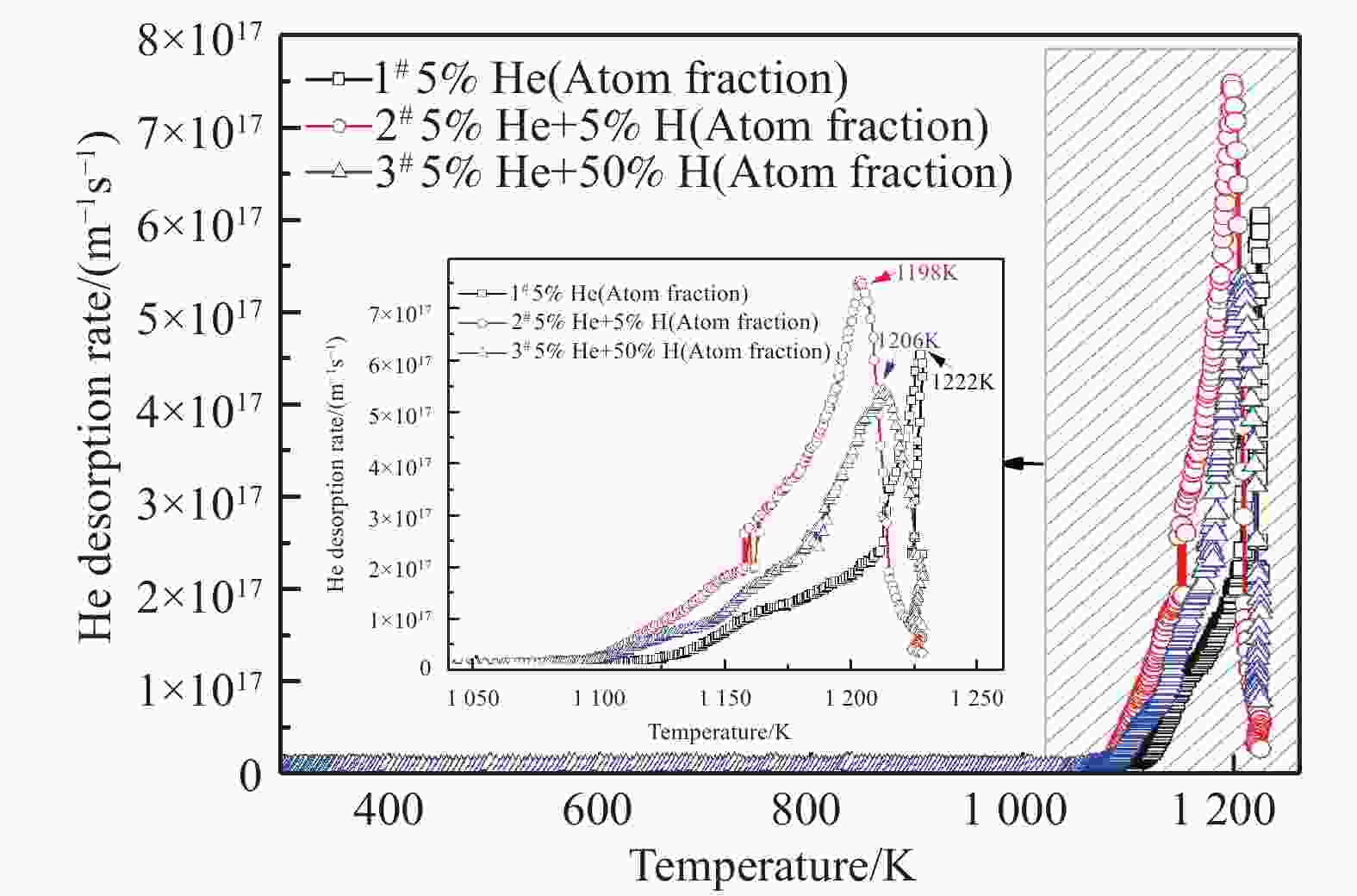
Figure 3. (color online)The comparison of TDS spectra between the He+-alone (sample 1#) and the He++H2+ sequential irradiation (samples 2# and 3#).
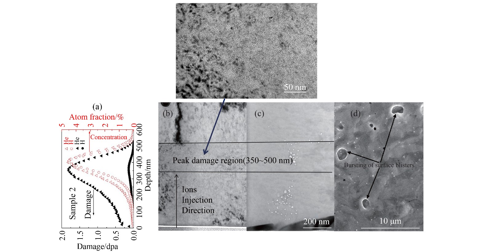
Fig. 4 shows the process of He release via bubble migration mechanism. It was noted that the small bubbles with high density formed in the peak damage region (350~500 nm) during the He++H2+ sequential irradiation[Fig. 4(a) and (b)]. During the TDS test, these bubbles grew gradually by absorbing the mobile thermal vacancies or He atoms at lower temperatures. When the temperature reached the one at which the bubbles could become mobile, they started to migrate toward sinks such as grain boundaries, dislocations, and precipitates or the surface of the sample [Fig. 4(c)] due to the vacancy gradient between the thermal vacancy source and over-pressured bubble concentration[26]. Once migrated to the near surface, the bubbles could continue to grow via migration and coalescence or Ostwald ripening mechanism[27-28]. The continued growth of bubbles could cause blistering of the surface until the bursting of blisters in the end [Fig. 4(d)], accompanied by the release of a large number of He.
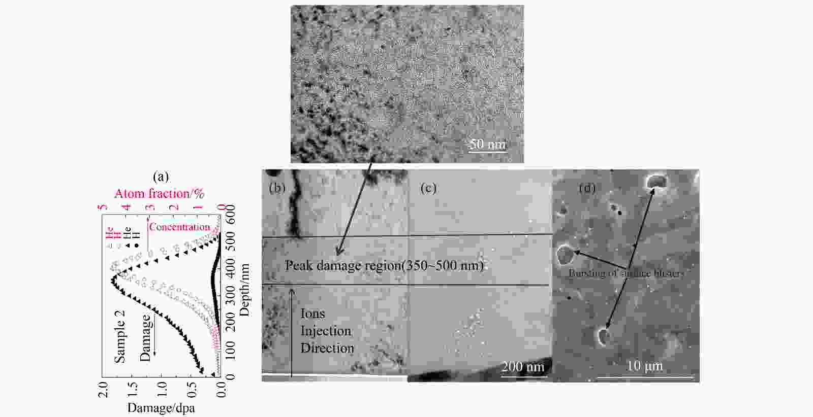
Figure 4. (color online)The process of He release from the bubbles(as the sample 2): (a) the depth profiles of damage level and He/H concentration under He++H2+ sequential irradiation; (b) bubbles nucleation during the irradiation; (c) bubbles coarsening and migrating to the surface; (d) He release via bursting of the surface blisters.
After the TDS measurements, He bubble retention was observed by TEM. The result (Fig. 5) shows that some He bubbles with various sizes were distributed around the dislocations (in samples 1# and 3#) and in the precipitates (in samples 2# and 3#). It is known that both dislocations and precipitates are strong sinks for point-defects and small point-defect clusters, including He atoms or He bubbles[13]. The bubble prefers to move toward them and coalescence to grow rather than migrate to surface during heating. As a consequence, there are some bubbles trapped by dislocations and precipitates. In addition, according to the previous report, if the pathway to specimen surfaces can be set up via interlinking of the bubbles at the grain boundary, the grain boundaries can be as the prior channel for the He bubble release[26]. Base on this assumption, it is possible that there were some bubbles hold-up at the grain boundaries. Unfortunately, no grain boundary was found in all of the TEM samples. Another case is that the pressure inside the bubbles was not high enough to burst, although the bubbles had moved near the surface. All of these factors can lead to the He bubble retention.
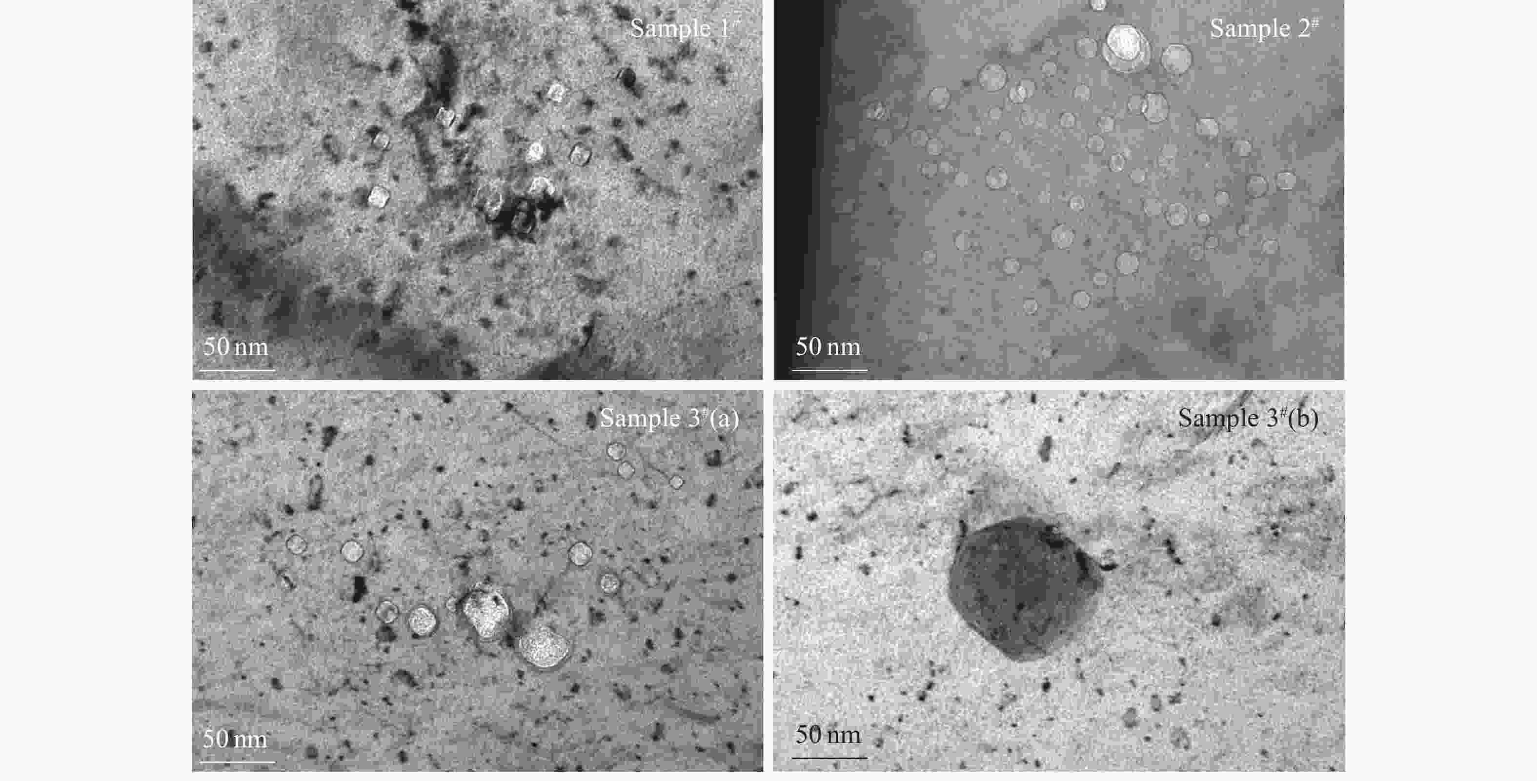
Figure 5. The retention of bubbles in the H/He irradiated samples after the TDS measurements (under-focus of 1.5 µm). Some He bubbles with various sizes were observed around the dislocations (in samples 1# and 3#(a)) and in the precipitates (in samples 2# and 3#(b)).
-
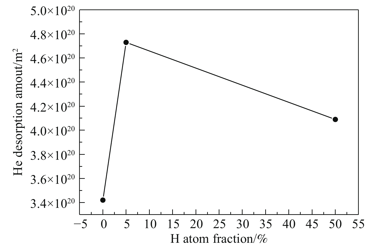
Fig. 3 shows that the major peak shifts to lower temperatures under the He++H2+ sequential irradiation, compared to that under the He+-alone irradiation. Correspondingly, the total amount of He desorption increases from 3.4×10²⁰ to 4.7×10²⁰ atoms/m2 (Fig. 6). This indicates that the He thermal desorption is enhanced by additional H irradiation. However, as the peak concentration of H increases from 5% to 50% (atom fraction), the peak temperature increases and the peak desorption rate decreases, oppositely. Meanwhile, the total amount of He desorption decreases to 4.1×10²⁰ atoms/m2. This suggests that when the fluence of H irradiation is sufficiently high, the He thermal desorption is suppressed to a certain extent.
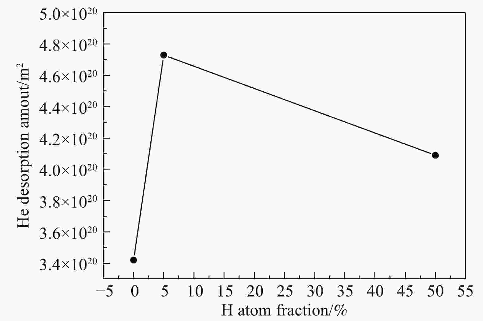
Figure 6. The total amount of He desorption as a function of the H concentration (atom fraction) for the He++H2+ sequential irradiation.
As mentioned above, the dissociation of He from the bubbles includes two processes during the TDS heating: bubbles migration to the surface and coarsening of bubbles near the surface.
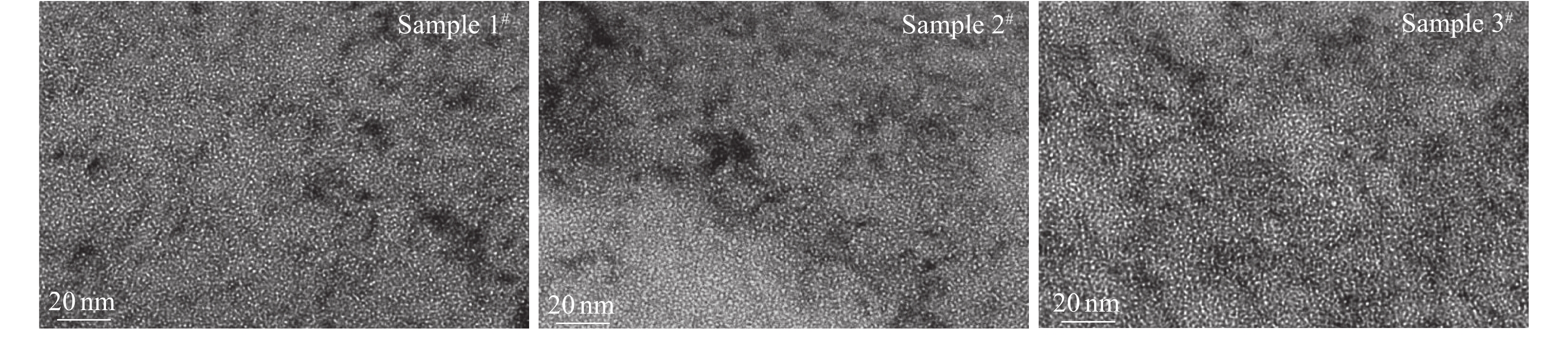
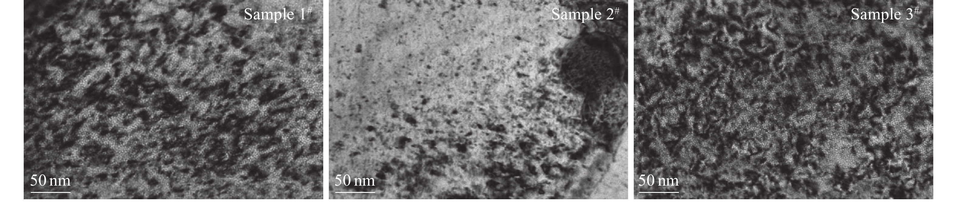
The first process is related to the characteristic (such as the type and size) and distribution of bubbles before the TDS test. Fig. 7 shows the TEM bright field images of bubble morphology under the under-focus conditions. As can be seen from the statistics (Table 3), there is no apparent difference in the size of the visible bubbles with and without additional H irradiation under the TEM observation. This is because that the size of bubbles is largely affected by the irradiation temperature[29]. The bubble size is generally smaller under the irradiation at room temperature. However, the density of the bubbles increases slightly by the additional H irradiation. From this, it can be concluded that the bubble nucleation was enhanced due to additional vacancies introduced by H irradiation. As a result, the probability of bubbles migration to surface increases, thereby leading to the increased fraction of He release by the mechanism of bubble migration in the end.
Table 3. The average size and density of bubbles in all the irradiated samples.
Samples Average diameter/nm Density/(1024/m3) 1# (He) 0.73±0.19 3.57±0.14 2# (He+H) 0.69±0.17 4.14±0.27 3# (He+H) 0.75±0.18 4.28±0.23 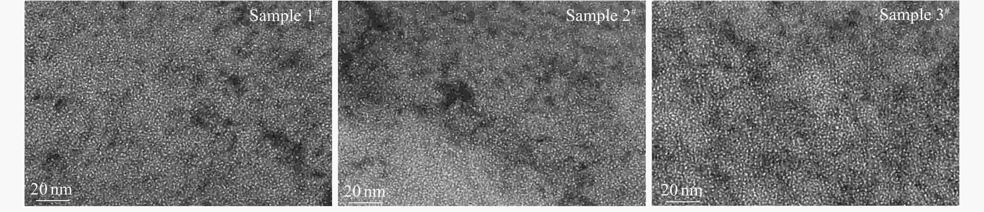
Figure 7. TEM morphology of bubbles in the samples 1#, 2# and 3# (under-focus of 300 nm) before the TDS test.
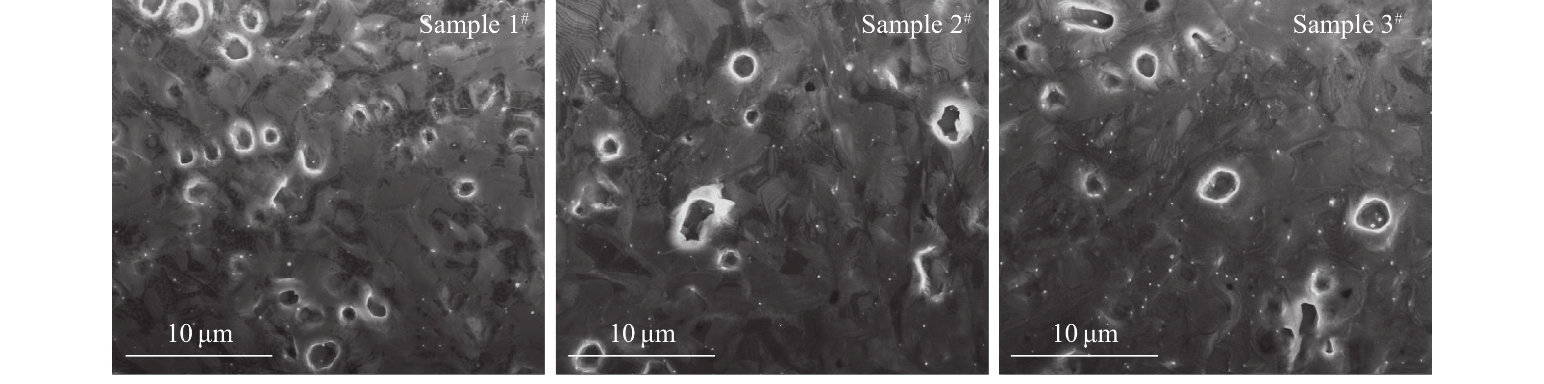
Fig. 8 shows that the blisters observed on the surfaces of the He++H2+ sequential irradiated samples (2# and 3#) are fewer and larger than those observed on the surface of the He+-alone irradiated sample (1#). This reveals that the growth of bubbles near the surface was promoted by the additional H irradiation[30-31]. Compared with those in the He+-alone irradiated sample, the bubbles in He++H2+ sequential irradiated samples had grown into larger bubbles preferentially during TDS test. The pressure inside these bubbles was high enough to make the bubbles break through the surface and burst at a lower temperature. As a result, more quantity of He atoms was released from the larger bubbles.
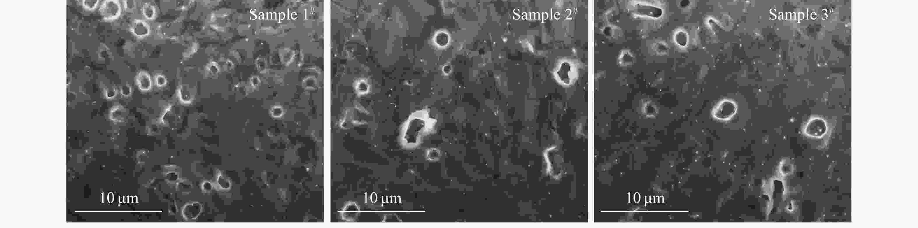
Figure 8. SEM images of the samples 1#, 2# and 3# after the TDS measurements for comparison of broken blisters on the surface.
In the case of H irradiation with the peak concentration of 5% (atom fraction), the damage level induced by H is lower (Fig. 1) and the ratio of vacancy to He shows a little increase (Fig. 2). However, the concentration of H introduced is almost the same as that of He. It means that the enhancement of the He thermal desorption mainly was attributed to the presence of H atoms. One explanation is that H can lower the pressure needed to deform the material[32-33].Thus the blister is able to grow more easily. An alternative explanation is that H can promote the growth of He bubble near the surface[34], resulting in the early release of He via bursting of blisters at the lower temperature.
However, when the peak concentration of H increased to 50% (atom fraction), the damage level induced by H (1.4 dpa at peak) is quite higher than that induced by He (1.8 dpa at peak). It can be inferred that, as additional displacement damages introduced by the H irradiation increases, the nucleation of dislocation loop is facilitated due to the excess interstitials left by the process of bubble nucleation[35]. As shown in Fig. 9, the irradiation-induced dislocation loops were observed in the irradiated samples. Unfortunately, the specific details were difficult to identify. It has been indicated that the interaction between the dislocation loops and the bubbles during their thermal evolution can inhibit the release of He bubbles[36-37]. Furthermore, as mentioned above, the original precipitation in the sample is also obstacles to bubble migration. With the increase of the additional displacement damages, the number of He bubbles which could migrate to the surface was reduced during heating. Therefore, the average size of the blisters observed in sample 3# is smaller than that of sample 2# (Fig. 8).
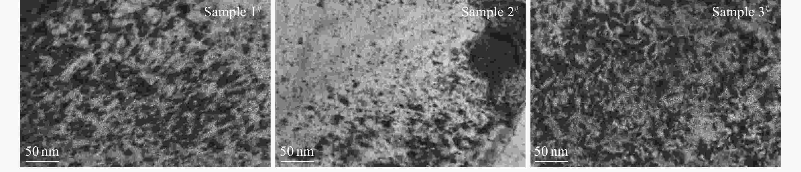
Figure 9. The TEM images of the irradiation-induced dislocation loops in the samples 1#, 2# and 3#.
In order to further understand the influence of dislocation and precipitation (including original and irradiation-induced) on He release, the thermal evolution behavior of dislocation and precipitation and their interaction with He bubble should be studied in detail in the future.
-
In this study, the alone irradiation of He+ and the sequential irradiation of He+ and H2+ were performed on SIMP steel at room temperature to investigate the effects of H on both He bubbles evolution and He release behaviors. The TDS results show that a major peak at 1 198~1 222 K was observed in all the irradiated samples. This is attributed to the bursting of surface blisters as a result of the increase of pressure inside the bubbles which migrated to the surface with increasing temperatures during the TDS heating. For the He++H2+ sequential irradiation, when the peak concentration of H increased to 5% (atom fraction), the major peak shifted to lower temperature than that for the He+-alone irradiation. The SEM results show that the larger blisters were observed in the He++H2+ sequential irradiated samples than that in the He+-alone irradiated sample after TDS measurements. This indicates that the growth of blisters near the surface was enhanced by H, resulting in the enhancement of He release. However, when the peak concentration of H increased to 50% (atom fraction), He retention was enhanced, oppositely, due to an increase in the additional displacement damages introduced by the H irradiation.
-
摘要: 为了初步理解核用结构材料中H对He行为的影响,以He离子单独辐照和He和H离子连续辐照作为对比,利用热释放谱(TDS)、透射电子显微镜(TEM)和扫描电子显微镜(SEM)研究了SIMP中H对He的热解吸和滞留行为的影响。TDS结果表明:He释放的主峰主要出现在1 198~1 222 K之间,对应于气泡的迁移释放机制。相对于He单独辐照,H的附加辐照使得He的释放峰向低温移动,且释放量增大。即H促进了He的热解吸。另外,H对He热解吸的促进作用与H的辐照剂量有关。当H注入的峰值浓度(原子分数)从5%增加到50%时,这种促进作用有所减弱。结合TEM和SEM结果发现:H的存在促进了TDS加热过程中材料表面的起泡行为,从而加速了He以气泡迁移机制释放的过程。
-
关键词:
- SIMP steel /
- H/He irradiation /
- thermal desorption /
- bubble
Abstract: In order to provide a basic understanding on the effect of H on He behaviors in the structural materials for the future nuclear systems, the effect of H on He thermal desorption and retention behaviors in SIMP steels was studied using thermal desorption spectroscopy(TDS), scanning electron microscope(SEM), and transmission electron microscopy(TEM) by comparing the results of the alone irradiation of 130 keV He+ and the sequential irradiation of 130 keV He+ and 160 keV H2+. The TDS results show that a major peak of He release occurred in the temperature of 1 198~1 222 K via the mechanism of bubble migration. The peak temperature of He release was lower and the release amount was larger under the sequential irradiation of He+ and H2+ than that under the He+-alone irradiation. This indicates that He desorption was enhanced by the additional H irradiation. In addition, the enhancement effect of H on He thermal desorption depends on the dose of H irradiation. When the peak concentration of H increased from 5% to 50% (atom fraction), this enhancement effect was weakened. Combined with TEM and SEM results, it was found that the presence of H promoted the surface blistering during TDS heating, thus accelerating the release of He by the mechanism of bubble migration.-
Key words:
- SIMP steel /
- H/He irradiation /
- thermal desorption /
- bubble
-
Figure 1. (color online)The depth profiles of damage level and He/H ions concentrations in the samples 1#, 2# and 3#, respectively, according to SRIM 2013 calculations.
Figure 2. (color online)The ratio of vacancy to He in the samples 1#, 2# and 3#, respectively.
Figure 3. (color online)The comparison of TDS spectra between the He+-alone (sample 1#) and the He++H2+ sequential irradiation (samples 2# and 3#).
Figure 4. (color online)The process of He release from the bubbles(as the sample 2): (a) the depth profiles of damage level and He/H concentration under He++H2+ sequential irradiation; (b) bubbles nucleation during the irradiation; (c) bubbles coarsening and migrating to the surface; (d) He release via bursting of the surface blisters.
Figure 5. The retention of bubbles in the H/He irradiated samples after the TDS measurements (under-focus of 1.5 µm). Some He bubbles with various sizes were observed around the dislocations (in samples 1# and 3#(a)) and in the precipitates (in samples 2# and 3#(b)).
Figure 6. The total amount of He desorption as a function of the H concentration (atom fraction) for the He++H2+ sequential irradiation.
Figure 7. TEM morphology of bubbles in the samples 1#, 2# and 3# (under-focus of 300 nm) before the TDS test.
Figure 8. SEM images of the samples 1#, 2# and 3# after the TDS measurements for comparison of broken blisters on the surface.
Figure 9. The TEM images of the irradiation-induced dislocation loops in the samples 1#, 2# and 3#.
Table 1. The chemical compositions of SIMP steel*.
Elements Mass fraction/% Elements Mass fraction/% C 0.22 Ta 0.12 Si 1.22 V 0.18 Cr 10.24 S 0.0 043 Mn 0.52 P 0.004 W 1.45 Fe Bal. * Normalizing 0.5 h at (1 040±10) ℃ and tempering 1.5 h at (760±10) ℃.  下载: 导出CSV
Table 2. The detailed parameters in the He/H irradiation.
Samples Ions Energy/keV Fluences/(ions/cm2) Peak damage/dpa Peak atom fraction/% 1# (He) He+ 130 7.14×10¹⁶ 1.8 5 2# (He+H) He+ 130 7.14×10¹⁶ 1.8 5 H2+ 160 2.78×10¹⁶ 0.14 5 3# (He+H) He+ 130 7.14×10¹⁶ 1.8 5 H2+ 160 2.78×10¹⁷ 1.4 50
下载: 导出CSV
Table 3. The average size and density of bubbles in all the irradiated samples.
Samples Average diameter/nm Density/(1024/m3) 1# (He) 0.73±0.19 3.57±0.14 2# (He+H) 0.69±0.17 4.14±0.27 3# (He+H) 0.75±0.18 4.28±0.23
下载: 导出CSV
-
[1] CABET C, DALLE F, GAGANIDZE E, et al. J Nucl Mater, 2019, 523: 510. doi: 10.1016/j.jnucmat.2019.05.058 [2] YANG K, YAN W, WANG Z G, et al. Acta Metall Sin, 2016, 52: 1207. (in Chinese) doi: 10.11900/0412.1961.2016.00320 [3] LI Y F, SHEN T L, GAO X, et al. Chin Phys Lett, 2014, 31: 036101. doi: 10.1088/0256-307X/31/3/036101 [4] ZHU H P, WANG Z G, GAO X, et al. Nucl Instr Meth B, 2015, 344: 5. doi: 10.1016/j.nimb.2014.11.051 [5] WANG J, GAO X, WANG Z G, et al. Chin Phys Lett, 2015, 32: 076101. doi: 10.1088/0256-307X/32/7/076101 [6] LI Y F, SHEN T L, GAO X, et al. Chin Phys Lett, 2013, 30: 126101. doi: 10.1088/0256-307X/30/12/126101 [7] CUI M H, WANG J, WANG Z G, et al. Nucl Instr Meth B, 2017, 406: 611. doi: 10.1016/j.nimb.2017.01.083 [8] DAI Y, ODETTE G R, YAMAMOTO T. The Effects of Helium in Irradiated Structural Alloys [M]. Amsterdam: Elsevier, 2012: 141. [9] ODETTE G R, ALINGER M J, WIRTH B D. Annu Rev Mater Res, 2008, 38: 471. doi: 10.1146/annurev.matsci.38.060407.130315 [10] VLADIMIROV P, MÖSLANG A. J Nucl Mater, 2006, 356: 287. doi: 10.1016/j.jnucmat.2006.05.037 [11] MARIAN J, HOANG T, FLUSS M, et al. J Nucl Mater, 2015, 462: 409. doi: 10.1016/j.jnucmat.2014.12.046 [12] MALITCKII E. Hydrogen and Helium Effects on Reduced Activation Fe-Cr Ferrite-Martensite and ODS Steels[M]. Finland: Aalto University Press, 2015: 22. [13] WAS G S. Fundamentals of Radiation Materials Science[M]. New York: Springer, 2017: 464. [14] KANO F, ARAI Y, FUKUYA K, et al. J Nucl Mater, 1993, 203: 151. doi: 10.1016/0022-3115(93)90051-y [15] TOLSTOLUTSKAYA G D, RUZHYTSKIY V V, KOPANETS I E, et al. J Nucl Mater, 2006, 356: 136. doi: 10.1016/j.jnucmat.2006.05.022 [16] KING D A. Surf Sci, 1975, 47: 384. doi: 10.1016/0039-6028(75)90302-7 [17] KUPRIIYANOVA Y E, BRYK V V, BORODIN O V, et al. J Nucl Mater, 2016, 468: 264. doi: 10.1016/j.jnucmat.2015.07.012 [18] ZIEGLER J F, ZIEGLER M D, BIERSACK J P. Nucl Instr and Meth B, 2010, 268: 1818. doi: 10.1016/j.nimb.2010.02.091 [19] STOLLER R E, TOLOCZKO M B, WAS G S, et al. Nucl Instr and Meth B, 2013, 310: 75. doi: 10.1016/j.nimb.2013.05.008 [20] SHEN Z Y, GUO L P, ZHANG W P, et al. Materials (Basel), 2018, 11: 1523. doi: 10.3390/ma11091523 [21] KIMURA A, SUGANO R, MATSUSHITA Y, et al. J Phys Chem Solids, 2005, 66: 504. doi: 10.1016/j.jpcs.2004.07.012 [22] ZELENSKIJ V F, NEKLYUDOV I M, RUZHITSKIJ V V, et al. J Nucl Mater, 1987, 151: 22. doi: 10.1016/0022-3115(87)90051-1 [23] VASSEN R, TRINKAUS H, JU NG, P. Phys Rev B, 1991, 44: 4206. doi: 10.1103/physrevb.44.4206 [24] BINYUKOVAL S Y, CHERNOV I I, KALIN B A, et al. J Nucl Mater, 2007, 367-370: 500. doi: 10.1016/j.jnucmat.2007.03.110 [25] CARVALHO I, SCHUT H, FEDOROV A, et al. J Nucl Mater, 2013, 442: 377. doi: 10.1016/j.jnucmat.2013.08.022 [26] EVANS J H, VEEN A V. J Nucl Mater, 1996, 233-237: 1179. doi: 10.1016/s0022-3115(96)00119-5 [27] CHERNIKOV V N, TRINKAUS H, JUNG P, et al. J Nucl Mater, 1990, 170: 31. doi: 10.1016/0022-3115(90)90323-f [28] GAO J, BAO L M, HUANG H F, et al. Nucl Instr and Meth B, 2017, 399: 62. doi: 10.1016/j.nimb.2017.03.148 [29] MIYAMOTO M, WATANABE T, NAGASHIMA H, et al. Phys Scr, 2014, T159: 014028. doi: 10.1088/0031-8949/2014/T159/014028 [30] WAKAI E, KIKUCHI K, YAMAMOTO S, et al. J Nucl Mater, 2003, 318: 267. doi: 10.1016/S0022-3115(03)00122-3 [31] SHEN Z Y, ZHENG Z C, LUO F F, et al. Fusion Eng Des, 2017, 115: 80. doi: 10.1016/j.fusengdes.2017.01.001 [32] ABRAMOV E, SHI S Q, THOMPSON D A, et al. J Nucl Mater, 1991, 186: 61. doi: 10.1016/0022-3115(91)90353-9 [33] ABRAMOV E. J Nucl Mater, 1994, 212-215: 1384. doi: 10.1016/0022-3115(94)91055-3 [34] XU Q, ZHANG J. J Nucl Mater, 2016, 479: 255. doi: 10.1016/j.jnucmat.2016.07.032 [35] LEE E H, HUNN J D, RAO G R, et al. J Nucl Mater, 1999, 271: 385. doi: 10.1016/s0022-3115(98)00722-3 [36] ZHU T, JIN S X, GONG Y H, et al. J Nucl Mater, 2017, 495: 244. doi: 10.1016/j.jnucmat.2017.08.027 [37] ZHOU Q L, AZUMA K, TOGARI A, et al. J Nucl Mater, 2018, 502: 289. doi: 10.1016/j.jnucmat.2018.02.035 -

 点击查看大图

计量
- 文章访问数: 780
- HTML全文浏览量: 221
- PDF下载量: 44
- 被引次数: 0
 甘公网安备 62010202000723号