-
In 1969, the idea of using laser produced plasma as an ion source was first proposed by Peacock and Pease[4]. During that decade, a number of efforts had been laid in development of high-performance laser ion sources(LISs)[5-8]. LISs have two prominent advantages over other highly charged ion sources: first is the ability to evaporate and ionize any element in principle, and second is the high ion current density (j>10 mA/cm2) that can be achieved at a distance of 1 m from the target surface. This high ion current density is orders of magnitude higher than other highly charged ion sources, such as EBISs (electron-beam ion sources) and ECRISs (electron cyclotron resonance ion sources). So they can be considered as the promising candidates for the ion sources in heavy ion cancer therapy facilities and the future accelerator complexes[9]. With the broad spectra of the ion kinetic energies and the variety of the ion charge states[10-11], LISs can also be applied to ion implantation[12].
In heavy ion accelerator applications, high intensity and high charge state of the produced ion beams are the two main development directions for laser ion sources. For high-Z materials, higher charge states can be achieved by using higher laser energy to increase the laser power density at the target[13]. For the practical application of LISs, the extracted ion beams are required to have a high current intensity and a reasonably long pulse duration. For example, in the High Intensity heavy ion Accelerator Facility(HIAF) project, tens of emA highly charged heavy ion beams with 10 μs pulse width are required[14]. However, the intrinsic properties of LISs determine that the current density j is inversely proportional to the cube of the drift length L, the distance from the target surface to the extraction point, and the pulse width τ proportional to the L. So, it is difficult for LISs to obtain a long pulse width while ensuring high current intensity, and usually a compromise between the current intensity and ion pulse duration is required to be made. Till now, the longest ion pulse durations for highly charged ions ranges from 3~15 μs, depending on the ion species[15-16]. These results were obtained for the plasma expansion length of 3 m with the laser ion source developed by the Institute of Theoretical and Experimental Physics(ITEP), with an atonement of ion yields to some extent.
In order to solve the conflict between the current intensity and ion pulse duration, a solenoid magnetic field is introduced in the present work to suppress the lateral expansion of laser ablation plasma(LAP). The experimental results of our team and Okamura's team had shown that the solenoid can extend the pulse width of the ion beams effectively and more importantly shows modulation effect on the temporal structure of the pulses of the LISs[2, 17-18]. In these investigations, the solenoids are usually located at the distance of tens of centimeters away from the target surface, so that the initially hot and dense plasma can be cooled and diluted during the adiabatic expansion with an introduction of magnetic field. This results into the plasma ratio (β) (i.e., plasma thermal pressure to the magnetic pressure) much less than the unity, suggesting the influence of solenoid magnetic field on plasma expansion behavior. The electrons will take the helical motions along the magnetic field lines in the solenoid region. For the ions, the gyroradius is larger by three orders in comparison with the electrons and is close to the transverse dimension of the drift tube, predicting the confinement of ions by the electrostatic field of confined electrons and not directly by the solenoid field.
Although the confinement effect of the solenoid on laser produced plasma has been demonstrated in previous researches, but some issues are still left opened. Due to the space limitation, the extraction point of the ion beams is usually located beyond the field of the solenoid, especially in the case of DPIS(direct plasma injection scheme), in which the ion beams are extracted just before the vanes of the RFQ. It is well known that plasma will expand along the diverging magnetic lines, so, whether the confinement effect can still be maintained at the edge of magnetic field is still an open question. In this study, the plasma with different density was produced by different laser energy and then confined with different magnetic field. The experimental results show that the plasma density got enhanced and concentrated even at the edge of the magnetic field and the relevant details of the present study have been discussed in the below sections.
-
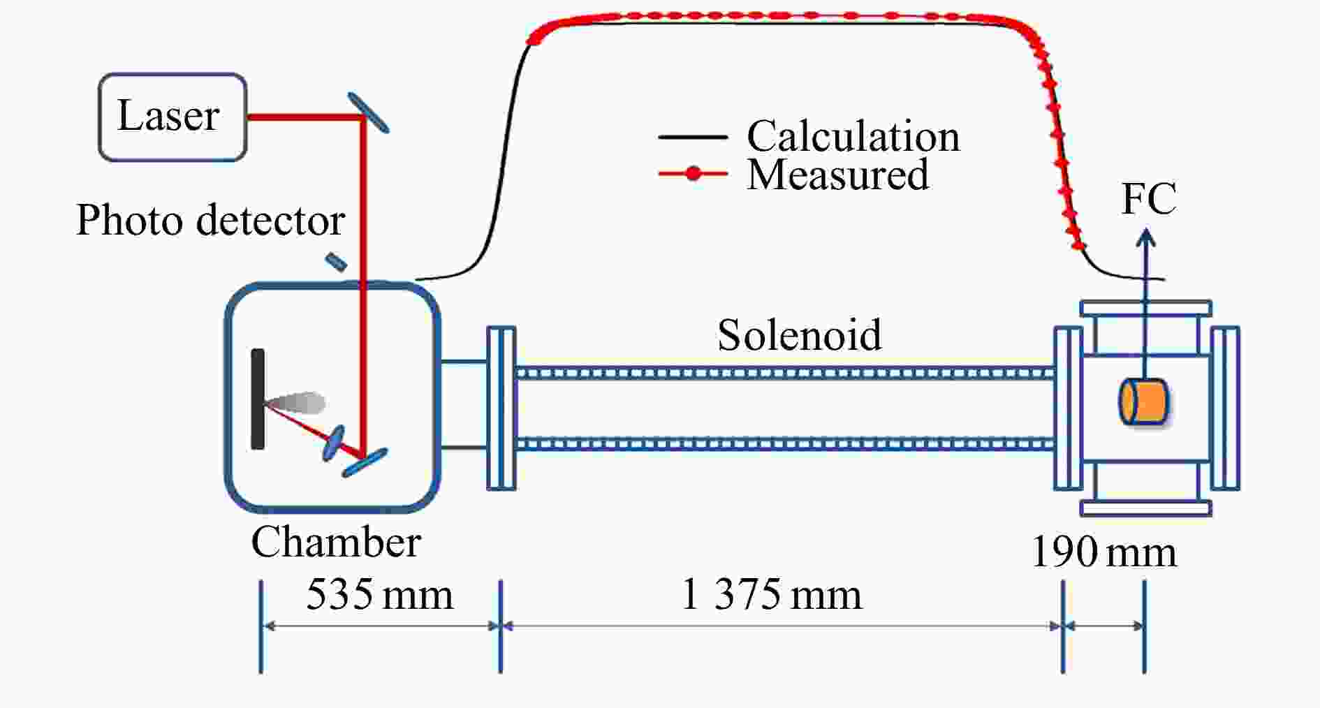
The layout of the experimental setup has been shown in Fig. 1. The LIS system is mainly composed of four parts: a laser system, target chamber, plasma drifting tube, and an ion beam diagnostic devices.
A Q-switched Nd:YAG laser system was used in the experiment. The laser energy was adjustable from 1 to 8 joules within a duration of 8 ns and a wavelength of 1 064 nm. The laser beam was transmitted for several meters in air by several high reflection flat mirrors until it goes into the target chamber and finally focused onto the carbon target at 20° incidence angle by a plano-convex lens with a focal length of 100 mm. The divergence of the laser beam had been determined as 0.2 mrad in the far-field measurement. Then the lens of 100 mm focal length would give a focal spot of 20 μm in diameter. The laser power density at the focal spot was estimated to be in the range of 2.4×10¹³ to 1.9×10¹⁴ W cm–2 for the laser energy of 1 to 8 J,
In order to measure the current intensity of the laser produced ion pulses and its temporal structure, a Faraday Cup(FC) was placed 2.1 m away from the target surface. The FC had an entrance aperture with a diameter of 3 mm and it can be moved in the direction perpendicular to the axis of the system. To separate the electrons in the plasma from the ions and avoid secondary electrons escaping from the FC, a suppressor voltage of –2.5 kV was applied to the cup. The value the suppressor voltage was determined with the following test. The ion current produced at 8 J laser energy was measured with the increasing absolute value of the suppressor voltage. The signal measured by the FC increased at first, and then saturated when the suppressor voltage was beyond –2.0 kV. So the voltage of –2.5 kV was enough to stop the electrons in the plasma and avoid the secondary electrons escaping in this study.
The solenoid used in this study had an inner diameter of 76 mm and a length of 1 375 mm. It was wound with 5 256 turns copper wire of diameter 2.1 mm in 8 layers. Before the experiment, we used a Gauss meter to measure the center magnetic field and it was found to agree well with the calculated value. It can give a magnetic field of 4.7×10⁻³ T/A at the center of the solenoid. The distance from the target surface to the inlet of the solenoid was 535 mm. The FC was located at 190 mm away from the exit of the solenoid, where the fringe field due to solenoid was almost negligible. For example, when the magnetic field at the center of the solenoid is 2.94×10⁻² T, the value at the FC is about 1.81×10⁻⁴ T.
-
In the experiment, a range of laser energy from 1 to 8 J was used to produce carbon plasma. The FC was moved in the lateral direction with the step of 8 mm to measure the transverse distribution of the laser produced ions. The target chamber and the drifting tubes were evacuated to about 10–4 Pa and 10–5 Pa, respectively. To ensure that every laser shot irradiates the target with the same surface condition, the target was shifted with a step of 1 mm after each laser shot by a three-dimensional manipulator. All the data presented in this article are the averages of five measured results under the same condition.
-
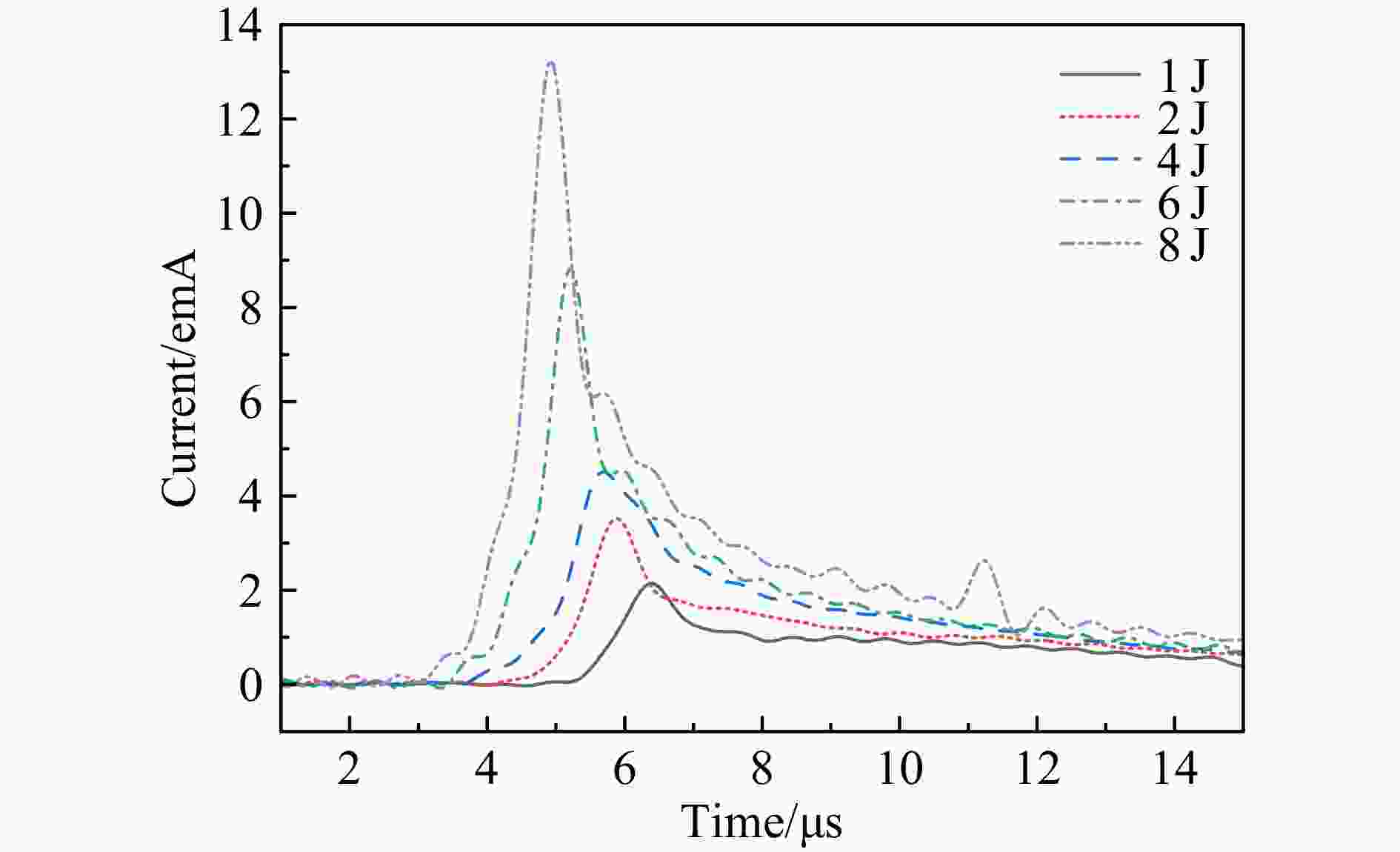
The signals of the carbon ion pulses produced at different laser energies are shown in the Fig. 2. The signal at every moment indicates the density of the detected plasma. And it is obvious that the plasma density produced by different laser energy is different. The peak current of the ion pulse increases with the laser energy, while the times of the rising edge and of the current peak decreases, suggesting the faster production of ions at high laser energies.
The current intensities of the ion pulses at different transverse positions, from R=0 to 32 mm, were measured with the help of the shiftable FC. The peak current, ion pulse duration—the full width at half with maximum and total charge in the pulse, which was obtained by integrating the pulse signal over time for the whole pulse duration, are plotted as the function of the laser energy for different transverse positions in Fig. 3. The peak current and total ion charge increase almost linearly with the laser energy for all the transverse positions presented here, agreeing well with the empirical formula of LAP[19], where the ion current density is directly proportional to the square of the focal spot diameter df and to the laser power density P, and hence is directly proportional to laser energy: J ∝ df2 P ∝ ELaser. Taking the statistical errors into account, the ion pulse duration is almost the same when the laser energy increases from 1 to 8 J. Nevertheless, if we consider the ion energy distribution, it is obvious that the ion energy distribution is narrower for higher laser energy, which is consistent with the previous work[14].

Figure 3. (color online)Total charge (a), peak current (b) and pulse duration (c) of the carbon ion pulses measured by FC at different transvers positions for different laser energy produced LAPs.
It is well known that the ion emission from laser ablation shows an angular dependence,
$J \propto {\cos ^k}\varTheta$ , where$\varTheta$ is the angle between the emitting direction and the target normal[20]. But it seems that there is no evident dependence of the ion current on the transverse position in our measurements. The reason is that the range of the emitting angle in our measurement is too small to exhibit the angular distribution of ion emission: even for the most peripheral position, R=32 mm, the emitting angle is only 0.87°. -
The plasma generated by different laser energy has different initial states. The response of LAP to the magnetic field confinement can be understood by applying magnetic confinement to the plasma. In the present experiment, we have loaded a solenoid magnetic field of different strengths to confine the LAPs, and to measure the lateral distributions of the LAPs.
All the ion parameters for the laser produced ions with the solenoid confinement, total ion charge, peak current, ion pulse duration, presented in the following part are normalized by the corresponding parameters for the ions without confinement. The normalized total ion charges are plotted as the functions of the magnetic field strength of the solenoid in Fig. 4 at different laser energy and radial positions. We know that the plasma will expand along the divergent magnetic field lines as long as it flows out of the solenoid. As mentioned above, the FC is located at the edge of the fringe field of the solenoid, where the magnetic field is almost negligible. Nevertheless, the evident enhancement of the ion population at the position of the FC show rise up with the application of magnetic field. This result is meaningful for the Direct Plasma Injection Scheme, in which the plasma nozzle is located close to the vanes of the RFQ and it is difficult to apply magnetic field in situ.
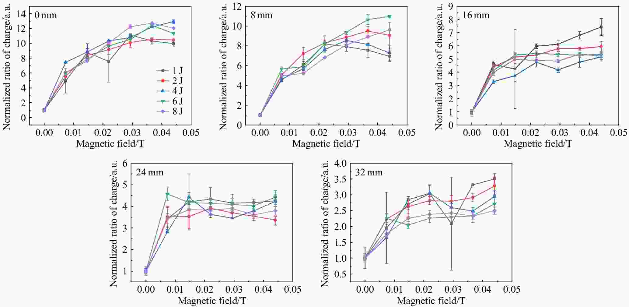
Figure 4. (color online)The normalized total ion charge varies with the magnetic field at different lateral positions.
Compared with the nearly uniform transverse distribution in the range of R=0 to 32 mm in the case of no magnetic confinement, there is obvious concentration trend with the applied magnetic field. This phenomenon could be explained as follows. The application of the magnetic field of the solenoid in the plasma expanding region limits the lateral expansion of the plasma to some extent[18]. But when the plasma expands into the fringe field of the solenoid, the spiraling motion of the electrons around the divergent magnetic field lines leads to the expanding of the plasma with an even wider angle than freely expanding. So it is more reasonable to note the axial position (390 mm from the FC) at which the magnetic field start to decrease as a new starting point for considering the expanding angle. Then in that case the position of R=32 mm corresponds to an expanding angle of 4.7°.
Comparisons of the enhancement factors of the total ion charge at different laser energies and magnetic field strengths, in general, show that the enhancement factor is higher at the central and the peripheral positions for higher and lower laser energies, respectively. This could be explained by the different initial conditions of the laser produced plasma by different laser energies. In our experiment, the higher laser energy corresponds to higher laser intensity at the focal spot. With increasing laser power density, the expansion angle of the produced plasma gets narrower and narrower, suggesting that the particles have higher longitudinal velocity and lower transverse velocity for higher laser energy, and the corresponding expansion angle will be narrower in the divergent magnetic field.
As shown in Fig. 4, the enhancement factor of total ion charge increases with the increasing magnetic field strength at first and thereafter saturates gradually. The saturation of the enhancement factor with the increasing magnetic field occurs for any radial position. But the applied magnetic field that makes the enhancement factor saturated is different for different radial position—the magnetic field is higher for the inner position while it is lower for the peripheral position. It means that the expanding angle gets narrower with the increasing magnetic field.
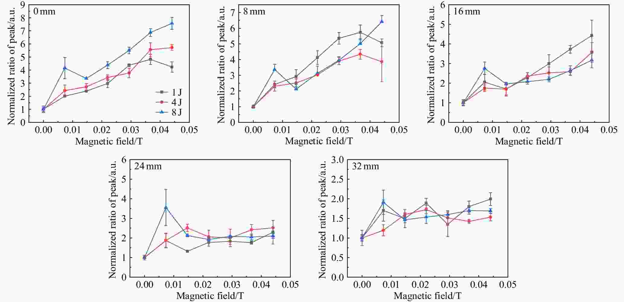
The enhancement factor of the peak current for different laser energy and different radial position has been plotted as the function of the applied magnetic field in Fig. 5. The behavior of the peak current is in general agreement with the ion total charge, and the enhancement of the peak current is lower than the total ion charge for the same condition. The discrepancy of the enhancement factors for the peak current and total ion charge is due to the different magnetic effects on the plasma with different initial parameters—plasma density, expanding velocity, velocity components etc. The enhancement of the total ion charge represents the average effect of the magnetic field on the whole plasma pulse.
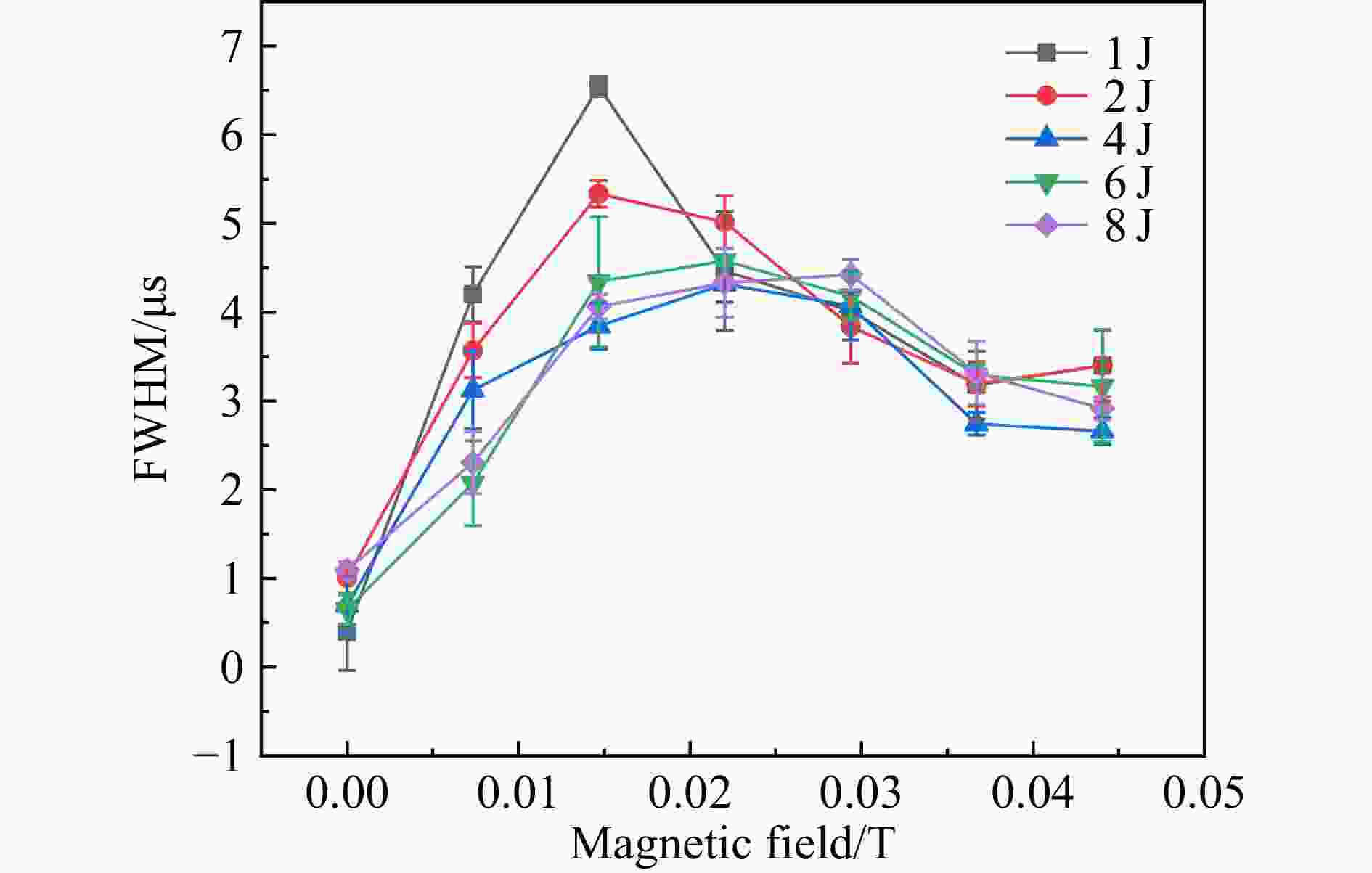
Fig. 6 shows the duration (full width of half maximum, FWHM) of the ion pulses measured at the system axis for different laser energy and magnetic fields. The ion pulse duration was observed to be prolonged to some extent for all laser energies with the applied magnetic field. This result can be suggested of importance for the application of laser produced plasma as an ion injector of accelerators. Only with a quite weak magnetic field, 7.34×10⁻³ T, the pulse duration can be increased prominently. But when the magnetic field increases further, the pulse duration becomes saturated and even tends to decrease. When the relatively low magnetic field is applied, the prolongation of the pulse duration is more obvious for lower laser energy. When the applied magnetic field gets stronger, above 2.0×10⁻² T, the ion pulse duration for all laser energy get close. This might indicate that magnetic field lower than 2.0×10⁻² T is not strong enough to confine the relatively dense plasma efficiently.
-
To suppress the lateral expansion of laser produced plasma, a solenoid was applied in the plasma expanding region. The radial distributions of the ions produced by different laser energy were measured with the help of a transversely shiftable FC at the edge of the fringe field of the solenoid for different magnetic field. Although the originally confined plasma has expanded in a divergent magnetic field before it reaches the FC, the enhancement effects are presented for all ion parameters like: total ion charge, peak current, and pulse duration. This result is important for the application of laser produced plasma in the Direct Plasma Injection Scheme-DPIS. Unlike the nearly uniform distribution of the plasma without magnetic field, the ion distribution shows an evident concentration trend when a magnetic field is applied. The confinement effects of the ions produced by different laser energy exhibit discrepancy because the magnetic effects on the plasma with different parameters are different. Last but not least, the duration of the ion pulse gets prolonged even with a weak magnetic field confinement. This is meaningful for the application of laser produced plasma as an ion injector of accelerators.
Acknowledgements This work is supported by National Natural Science Foundation of China(Grant Nos. 11722547 and 11505257) and Key Research Program of Frontier Sciences, CAS(Grant No. QYZDB-SSW-SLH041 and QYZDB-SSW-JSC025).
Characteristics of Laser Ablation Plasma in the Diverging Magnetic Field of a Solenoid
-
摘要: 激光烧蚀等离子体(LAP)可用作粒子加速器和离子注入器中使用的离子源。相较于其它离子源,激光离子源在流强上具有优势,但由于产生的离子束脉冲时间短,限制了其在加速器中的广泛应用。实验中通过对激光等离子体扩散区域引入螺线管磁场进行约束,实现了对激光等离子体脉冲时间结构的调制。为了研究螺线管磁场对LAP的影响,实验使用了不同的激光能量(1~8 J)来生产具有不同初始条件的激光等离子体,并应用了不同的磁场强度来约束激光等离子体。在螺线管边缘场,通过可移动的法拉第筒(FC)对激光等离子体的横向分布进行测量。对于不同初始状态的等离子体,随着磁场的增加,其离子脉冲的主要参数(脉冲总电荷量、峰值流强、脉宽)均呈现先上升后逐渐饱和的变化趋势。另外,在没有磁场的条件下,在所测量位置处,等离子体的横向呈均匀分布;而在磁场约束的条件下,等离子体明显向轴线聚集。以上实验结果对进一步了解磁约束激光等离子体的特性具有重要意义。Abstract: Laser ablation plasma(LAP) can be used as an ion source for particle accelerators and for ion implantation. Although the too intensive current intensity of laser ion sources give them advantages over other ion sources, yet the minute duration of laser produced ion pulses limits their applications in accelerators. By introducing a solenoid into the plasma expansion region, the modulation of the plasma temporal structure had been achieved[
1 -3 ]. In order to study the effect of solenoid magnetic field on LAP, we used different laser energies (1~8 J) to produce LAP at different initial conditions and applied various magnetic field strengths to confine the plasma. The transverse distribution of the laser produced ions were measured with a movable faraday cup (FC) at the edge of the fringe field of the solenoid. The main parameters of the ion pulses, the total charge, the peak current, and the pulse duration, enhanced at first and then got saturated with the increasing magnetic field, no matter what the initial plasma conditions were. Unlike the nearly uniform transverse distribution of the plasma without magnetic confinement, the plasma got concentrated when the magnetic field was applied. The experimental results presented and discussed in the present work are of great significance for further understanding the characteristics of magnetically confined LAP.-
Key words:
- laser ablation plasma /
- solenoid /
- magnetic field confinement
-
-
[1] TAKAHASHI K, KUZUMOTO M, MATSUMOTO Y, et al. Review of Scientific Instruments, 2020, 91: 033310. doi: 10.1063/1.5128633 [2] OKAMURA M, SEKINE M, IKEDA S, et al. Laser and Particle Beams, 2015, 33: 137. doi: 10.1017/S026303461500004X [3] SEKINE M, IKEDA S, ROMANELLI M, et al. Nucl Instr and Meth A, 2015, 795: 151. doi: 10.1016/j.nima.2015.05.030 [4] PEACOCK N J, PEASE R S. Journal of Physics D: Applied Physics, 1969, 2: 1705. doi: 10.1088/0022-3727/2/12/311 [5] GAMMINO S, TORRISI L, CAVALLARO S, et al. Review of Scientific Instruments, 2010, 81: 02A508. doi: 10.1063/1.3267291 [6] YEATES P, COSTELLO J T, KENNEDY E T. Review of Scientific Instruments, 2010, 81: 043305. doi: 10.1063/1.3374123 [7] GASIOR P.Can ICAN can CERN into a can: Review Study[C]//Photonics Applications in Astronomy, Communications, Industry, and High-Energy Physics Experiments 2013, October 23, 2013, Wilga, Poland. Bellingham: SPIE, 2013: 89030N. [8] IKEDA S, KUMAKI M, KANESUE T, et al. Review of Scientific Instruments, 2016, 87: 02A915. doi: 10.1063/1.4935785 [9] SAKO T, YAMAGUCHI A, SATO K, et al. Review of Scientific Instruments, 2016, 87: 02C109. doi: 10.1063/1.4935975 [10] ALNAIMI R. Time of Flight in Electrostatic Ion Analyser for Laser Produced Plasma ion Resolving[C]//Proc SPIE 11032, EUV and X-ray Optics: Synergy between Laboratory and Space VI, April 26, 2019, Prague, Czech Republic. Bellingham: SPIE, 2019: 11032K. [11] ALNAIMI R. Journal of Instrumentation, 2017, 12: 6001. doi: 10.1088/1748-0221/12/06/P06001 [12] ROSINSKI M, BADZIAK J, BOODY F P, et al. Vacuum, 2005, 78: 435. doi: 10.1016/j.vacuum.2005.01.064 [13] BALABAEV A, KONDRASHEV S, KONUKOV K, et al. Review of Scientific Instruments, 2004, 75: 1572. doi: 10.1063/1.1691512 [14] ZHAO Huanyu, ZHANG Junjie, JIN Qianyu, et al. Review of Scientific Instruments, 2016, 87: 02A917. doi: 10.1063/1.4937115 [15] FOURNIER P, GREGOIRE G, KUGLER H, et al. Review of Scientific Instruments, 2000, 71: 924. doi: 10.1063/1.1150347 [16] KONDRASHEV S, MESCHERYAKOV N, SHARKOV B, et al. Review of Scientific Instruments, 2000, 71: 1409. doi: 10.1063/1.1150471 [17] OKAMURA M, ADEYEMI A, KANESUE T, et al. Review of Scientific Instruments, 2010, 81: 02A510. doi: 10.1063/1.3267312 [18] WANG Guicai, ZHAO Huanyu, JIN Qianyu, et al. Review of Scientific Instruments, 2019, 90: 113302. doi: 10.1063/1.5128637 [19] BROWN I G, The Physics and Technology of Ion Sources [M]. Weinheim : Wiley-VCH Verlag GmbH & Co KGaA, 2004. [20] BADZIAK J, PARYS P, VANKOV A B, et al. Applied Physics Letters, 2001, 79: 21. doi: 10.1063/1.1381570 -


 下载:
下载:


 甘公网安备 62010202000723号